


- Details
- Zugriffe: 11709
Einstieg in den Umstieg von AGM/Gel Bleiakkumulatoren auf LiFePo4 Akkumulatoren.
erschienen im Palstek 1-2022
Dieser Bericht (vom Praktiker für den Praktiker) beschreibt die Analyse der Batterien, des Bordnetztes und gibt Hinweise zur Auswahl der Komponenten. Er entstand aus der Notwendigkeit heraus das Bordnetz teilweise zu erneuern, unter Berücksichtigung der vorhandenen Komponenten und gleichzeitig auf einen modernen Stand zu bringen. Nur wenn der Yachteigner seine Bordversorgung kennt, wird er sich im Notfall auch zu helfen wissen.
In diesem Teil werden die verschiedenen Energiequellen an Bord analysiert. Anschließend werden die Unterschiede der Akkutypen erläutert. Zum Schluss werden zwei unterschiedliche Lithium Akkus aus der engeren Wahl zur Verwendung vorgestellt. Der zweite Teil beschreibt den Selbstbau eines Lithium Akkus aus frei in Deutschland verfügbaren Komponenten von Herstellern, die schon Jahre auf dem deutschen Markt vertreten sind. Dieser Teil steht auf dem Palstek Server zum Download zur Verfügung.
Energiequelle Service Akku:
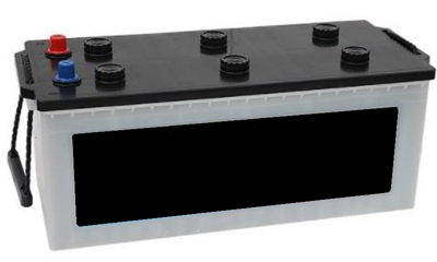
Auf den Starter Akku wird hier nur am Rande eingegangen, da er sich als Service Akku gar nicht eignet. Service Akkumulatoren sind für geringe bis kurzzeitig hohe Ströme ausgelegt. Sie haben eine geringe Selbstentladung und eine hohe Lade-/ Entlade Zykluszahl. Typischerweise werden AGM- oder Gel- Bleiakkumulatoren als Service Akkumulatoren verwendet.
Ist einer der Akkus handwarm, die anderen sind kalt? Das Gehäuse dieses Akkus zeigt kleine Rundungen? Das sind sichere äußere Zeichen für einen defekten Akku. Dieser muss sofort ausgesondert werden. Und wie kann man die Kapazität der verbliebenen Akkus feststellen?
Hochstromtester eignen sich nur für Starter Akkumulatoren und nicht für Service Akkumulatoren. Die einfachste Methode (nicht sehr genau aber einfach mit Bordmitteln durchzuführen) ist, den Akku voll aufzuladen und dann 8h - 12h ruhen zu lassen. Dann den Akku mit einem zwanzigstel der Kapazität (siehe Info) zu belasten. D.h. ein 200Ah Akku mit 10A, oder eine 80Ah Akku mit 4A. Mit ein paar Autoglühlampen kann man sich die notwendige Last zusammenbauen. 21W/5W Lampe = 1,75A/0,4A; 55W Abblendlicht = 4,6A; Ankerlicht = 2A;
Hier ein einfacher Akkukapazitätstest:
Den Akku aufladen und mindestens 8h-12h ohne Lader ruhen lassen. Dann mit einem zwanzigstel der Kapazität belasten und die Uhr starten. Wenn die Akkuspannung unter Last 11,8V erreicht hat wird die Zeit gestoppt:
· nach weniger als 6h ist die Akkukapazität < 60%. Nach meiner Meinung ist dann das Lebensende als Service Akkumulator erreicht.
· nach 8h ist die Kapazität um die 80%. %. Nach Meinung der Akkuhersteller ist dann das Lebensende als Service-Akkumulator erreicht.
· nach fast 10h hat der Akku noch die gesamte Kapazität.
Die Formel für die Kapazitätsberechnung lautet: Zeit(h) * Strom (A) *2 (da wir nur 50% entladen) = Kapazität in Ah.
Bei diesem Test wird der Akku zu 50% entladen. Anschließend muss der Akku sofort wieder aufgeladen werden, um Schäden zu vermeiden.
Info: Als Service Akkumulatoren werden typischerweise AGM oder Gel Akkus mit der Bezeichnung C20 verwendet. Das bedeutet bei einem Entladestrom von einem 20zigstel der Kapazität (200Ah Batterie è 10A Entladestrom) kann die (neue) Batterie die vorgesehene Kapazität liefern. Entnimmt man mehr Strom, hat der Akku weniger Kapazität, entnimmt man weniger, stellt der Akku mehr Kapazität zur Verfügung.Info:
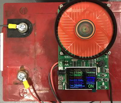
Eine genauere Methode ermöglicht die elektronische Last DL24. Sie eignet sich zum Test von aller Arten von Akkumulatoren, von Powerbänken bis zu Service Akkumulatoren. Der Laststrom ist von 0.0 – 20A einstellbar bei einer Gesamtverlustleistung von 150W. Laststrom und Endspannung einstellen und den Startknopf drücken. Nach Erreichen der Endspannung schaltet die Last automatisch ab und zeigt die entladenen mAh an. Die mAh mit 2/1000 multiplizieren. Das Ergebnis ist die Kapazität in Amperestunden (Ah) des Akkus. Der Akku sollte sofort wieder aufgeladen werden, da ein Bleiakku sonst zu sulfatieren droht. Das verkürzt die Lebensdauer (Kapazität) drastisch.
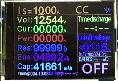
Hier wird eine 12V 200Ah AGM mit Is=10,00A belastet. Nach Timing: 004:10:03h wurde die Akkuspannung von 11,8V erreicht und 41,6Ah wurden entnommen. Somit wurde eine Restkapazität von 83,2Ah ermittelt. Das sind 41,2% Restkapazität eines 200Ah AGM-Akkus. Der Akkumulator hat somit das Lebensende als Service-Akkumulator an Bord erreicht.
Natürlich können die AGM Akkus noch eine Zeitlang genutzt werden. Mit zwei gebrauchten Solarpanel und einem alten PWM Regler kann ein Gartenhäuschen oder Lagerraum mit LED-Lampen gut beleuchtet werden.
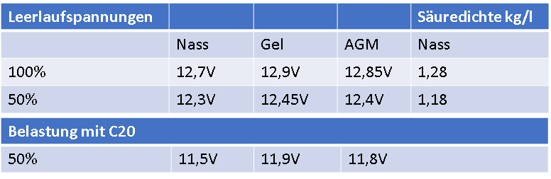
Nebenstehend eine Tabelle mit den typischen 50% Entladespannungen der verschiedenen Batterietypen.
Energiequelle: Landstromnetzteil
Ein ungeregeltes Akkuladegerät ohne Kennlinie, genauso wie ein offener Bleisäure Starter Akku, gehört nicht mehr an Bord.
Ein Landstromnetzteil sollte so leistungsfähig sein, um eine Service Akku (-Bank) innerhalb 10h-14h (über Nacht) zu laden. Es muss die Kennlinien der üblichen Bleiakkus (AGM, Gel, etc.), sowie Lithium Akkus enthalten. Ein Ladegerät mit 3 getrennten Ausgängen kann 3 Akkumulatoren individuell laden.
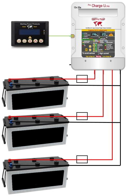
Bei einem leeren Akku werden bei einem 12V / 60A Ladegerät knapp 1000W aus dem Lichtstromnetz entnommen. Das kann für die Landstromsicherung in manchen Häfen (oder für einen an Bord befindlicher Generator) schon zu viel sein. Dann ist eine einstellbare Ausgangsleistung (100%, 75%, 50%, 25%) von großem Vorteil. Daher wurde schon vor Jahren das nebenstehende Landstromnetzteil in der 12V 60A Version plus Fernbedienung gewählt. Für die neue Konfiguration mit nur noch einem LiFePo4 Akkumulator werden die 3 Ausgänge zusammengeschaltet. Eine LiFePo4 - Kennlinie und eine individuelle Kennlinie steht in diesem Lader zur Verfügung. Das Ladegerät kann auch parallel weitere Verbraucher an Bord versorgen.
Zusätzlich gehört in jedem Akkuladekabel eine Streifensicherung mit 100A gegen Fehlfunktionen oder Überlast.
Energiequelle: Antriebsmaschine
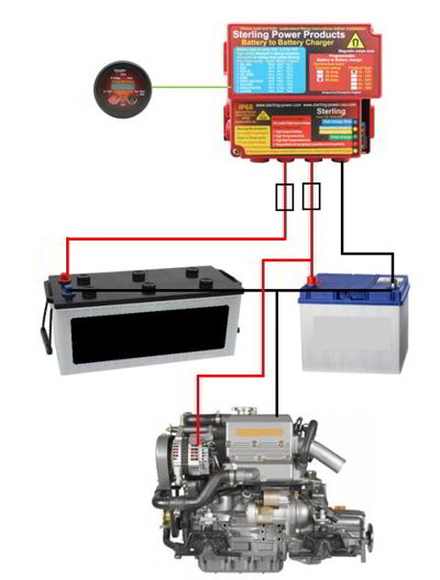
Die Antriebsmaschine hat Ihren eigenen Starter Akku und ist unabhängig von dem Serviceakkumulator. Als Notstartmöglichkeit kann (muss aber nicht) ein Notschalter eine Verbindung zwischen Service Plus und Starter Akku Plus herstellen. Ich habe diesen Schalter die letzten 15 Jahre nicht gebraucht.
Die Lichtmaschinen (Standard) liefern zwischen 80A und 125A. Leider unterstützen die Regler dieser Lichtmaschinen meistens nur die Eigenschaft von Starter Akkumulatoren (W-Kennlinie). Daher eignen sich diese Lichtmaschinen nicht zur Ladung von Service Akkus. Sie werden nie voll und es dauert endlos lange. Eine Änderung am Regler würde die Gewährleistung der Lichtmaschine aufheben.
Um doch mit einer Standardlichtmaschine (auch eine mit erhöhter Leistung) den Service Akku laden zu können, kommt hier ein „Batterie zu Batterie“ Lader (B2B-Lader, Ladebooster, 12V 60A) zum Einsatz.
Dieser B2B-Lader belastet die Lichtmaschine zusammen mit der Starter Akku auf 13,6V. Dabei versucht die Lichtmaschine mit 14,6V gegenzuhalten. Der B2B-Lader nimmt die Lichtmaschinen-Leistung auf und transportiert sie entlang einer einstellbaren Kennlinie in den Service Akkumulator (AGM, Gel, LiFePo4 oder Custom). So werden die Service Akkumulatoren auch vollgeladen. Unterhalb von 13,0V wird keine Leistung aus Lichtmaschine und dem Starter Akku entnommen. Der B2B Lader wechselt dann nach 2min in den Sleep Modus bis zum nächsten Motorstart.
Die beiden Batteriekabel zur Starter- und Service Akku werden mit jeweils 100A Streifensicherungen gegen Fehlfunktionen / Überlastung geschützt.
Info: Die Katamaran Segler haben meist 2 Antriebsmaschinen. Damit kommen locker 120A Ladestrom für den Service Akku zusammen. Ein LiFePo4 Akku nimmt diese Ladeleistung problemlos auf und setzt sie in Ladung um. Eine weitere Verkürzung der Ladezeiten ist die Folge.
Energiequelle: Solaranlage
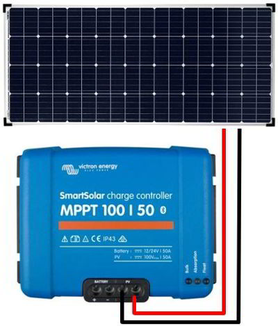
Um eine optimale Ladeleistung aus der Solaranlage herauszuholen, gilt es ein paar Grundregeln zu beachten.
- Ein Solarregler benötigt eine Panelspannung, die mindestens 5V höher ist als die Service Akkuspannung.
- Die Solarpanelspannung nimmt bei Erwärmung stark ab.
- Teilweise Abschattungen möglichst vermeiden.
Inzwischen gibt es Module auf dem Markt die nahezu unempfindlich gegen Abschattung sind. Bei diesen Modulen hat jede Zelle eine eigene Bypass Diode. (z.Bsp. AE-Solar)
- Ein 24V Solarpanel mit einem MPPT Regler kann auch einen 12V Service Akkumulator laden und ist unempfindlicher gegenüber Erwärmung.
- Am MPPT Regler können die Ladespannungen manuell eingestellt werden. MPPT Regler gibt es auch mit Bluetooth Interface.
Bei dem Austausch der Solaranlage wurden zwei 24V 180W Panels anstelle der 12V Panels eingebaut. Die Berücksichtigung der genannten Regeln hat sich vorteilhaft auf die Energiegewinnung ausgewirkt. Die Panels fingen schon mit der Morgensonne an die Batterien zu laden. Bei starker Erwärmung in der Mittagssonne wurden kaum Einbußen festgestellt.
Durch die programmierbare Kennlinie mit 8 verschiedenen Algorithmen kann der Solarregler auch die Anforderungen von LiFePo4 Batterien erfüllen. Zusätzlich können die Werte auch individuell eingestellt werden.
Dazu gibt es eine kostenfreie App für das Smartphone, mit dem sich die MPPT-Parameter Einstellungen auch abspeichern lassen.
Natürlich müssen die +Leitungen zum Service Akku mit 100A Streifensicherungen gegen Störungen und Überlast abgesichert werden.
Hinweis: Die naturbedingten variablen Ladelevel der Wind- und Solaranlagen sind Gift für die AGM Akkumulatoren, die immer gerne auf 100% Ladung gehalten werden wollen, um nicht zu sulfatieren. Gerade hier spielt die Lithium Technologie ihre Vorteile voll aus. Einer Lithiumzelle ist der Ladelevel fast egal.
Energiequelle: Generator
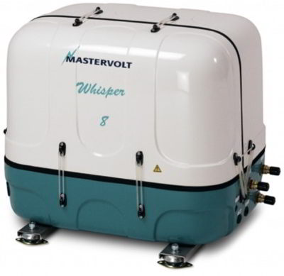
In den meisten Fällen liefern die OnBoard-Generatoren 1KW bis 5KW bei 230V. Die erzeugte Leistung wird in den Landstromanschluss an Bord eingespeist und durch das Landstromnetzteil in die Service Akkus geladen.
Ein weiterer Vorteil von Generatoren mit E-Starter: Der Generator wird mit dem Starter Akku der Antriebsmaschine verbunden. Die Lichtmaschine des Generators (40A) lädt die Starterbatterie der Antriebsmaschine und durch den B2B-Lader kommen weitere ca. 35A als Ladestrom für den Service Akku dazu. In Summe ein Ladestrom von fast 100A, die die LiFePo4 auch brav aufnimmt und Aufgrund der geringen Verluste in Ladung umsetzt. Die Ladezeiten (= Betriebszeiten) des Generators verkürzen sich dadurch weiter.
Hinweis: Auch die Laufzeiten der Generatoren kosten Geld. Wenn durch die Hochstromladbarkeit und die geringeren Ladeverluste der Lithium Technologie die Generatorlaufzeiten verkürzt werden können, wirkt sich das auf die Kosten aus. Genauso wie die dadurch verlängerten Wartungsintervalle, die weitere Kosten reduzieren.
Mythen und Wahrheiten über LiFeP04 im Vergleich zum Bleiakku.
Im Vergleich zu herkömmlichen Bleiakkumulatoren, können LiFePo4 nahezu komplett entladen werden, ohne dabei großartige Spannungseinbrüche zu erleiden. Während ein Bleiakku ca. 50% (Gel ca. 70%) seiner Nennkapazität abgeben kann (bei ca. 750 Ladezyklen), ist die Nennkapazität eines LiFePo4 Akkus nahezu auch die reale entnehmbare Kapazität (100% - 10% = 90%).
Ferner kennzeichnet sich der LiFePo4-Akku durch eine vergleichbare lange Lebensdauer. Die Akkus können 3.000 komplette Ladezyklen ohne kaum Verlust an Kapazität und an Spannung erreichen.
Wer seinen LiFePo4 Akku nur zu 30% entlädt, kann weit über 10.000 Zyklen erreichen. Der Akku hat dann noch 70% der Kapazität und ist weiter nutzbar.
Im negativen wie positiven Temperaturbereich haben die LifeYPo4 Akkumulatoren eine nützliche Erweiterung für Segler in den Barfußbreiten (+85°C statt 40°C) sowie im hohen Norden (-35°C statt 0°C). Daher sollte auch dieser Akkumulator Typ LiFeYPo4 betrachtet werden.
LiFePo4 Akkus sind empfindlich bezüglich Überladung und Temperatur. Eine Entladung ist bis zu
-35°C möglich, eine reversible Verringerung der Kapazität von ca. 15% (je nach Hersteller) muss dabei in Kauf genommen werden. Auch zu diesem Zweck ist die Verwendung eines Batteriemanagement Systems (BMS) Pflicht.
LiFePo4 sind teuer:
Häufig werden die Anschaffungspreise von LiFePo4 als ein Nachteil gegenüber Bleiakkus gesehen. Das stimmt nur bedingt, denn die lange Lebensdauer von über 3.000 bis weit über 10.000 Lade- und Entladezyklen lässt den Preis pro Wh weit unter dem Preis pro Wh von Blei-Akkus sinken.
Hierzu ein Rechenbeispiel:
Meine verbliebenen 2 x 12V 200Ah AGM müssen ersetzt werden. Kosten 450€ pro Stück. Den AGM Akku kann ich nur zu 50% entladen, damit ich ca. 750 Ladezyklen erhalte. Man kann auch mit 1.000 Ladezyklen rechnen. Die erhalte ich aber nur dann, wenn der Akku nach der Entladung innerhalb weniger Stunden wieder zu 100% voll aufgeladen wird. Das ist aber auf einem Boot meist nicht der Fall.
50% Entladung: 2 x 12V x 0,5 x 200Ah x 750zyklen = 1.800kWh für das Akkuleben.
900€ Batteriekosten/ 1.800kWh = 0,50€/kWh.
12V 400AH LiFePo4
50% Entladung: 12V x 0,5 x 400Ah * 10.000zyklen = 24.000kWh für das Akkuleben
3.400€ Akkusystemkosten/ 24.000kWh = 0,14€ / kWh
80% Entladung: 12V x 0,8 x 400Ah * 3.000zyklen = 11.520kWh
3400€ Akkusystemkosten/ 11.520kWh = 0,30€ / kWh
Eine Erhöhung der Entladung einer LifePo4 massive Vorteile in der realen, zeitlichen Nutzbarkeit bis zum nächsten Hafenaufenthalt oder Generatorladung bringt.
Gewicht: Beide 200Ah AGM wiegen 130kg, Ein LiFePo4 Akku mit 400AH+Zubehör wiegt 58kg. Gewinn 72kg.
Effizienz: AGM 80% - 90%; LiFePo4 98% - 99% Der Rest bis 100% geht in Wärme verloren. Gewinn 10% mehr Ladung aus dem Generator oder Solarpanel in den LiFePo4 Akku.
Ladezeiten: Alle kennlinienfähigen Ladegeräte laden AGM-Akkumulatoren in der ersten Stufe mit maximalem verfügbarem Strom, bis die Absorptions-Spannung erreicht wird. Dann ist der AGM Akku so ca. 80% - 85% geladen. Die Effizienz in diesem Ladungsabschnitt ist ca. 98%.
Dann wird mit konstanter Spannung bei stark abnehmenden Ladestrom geladen. Das dauert immer sehr viel länger als die erste Phase. So 8h-12h Ladezeit sind in dieser Stufe keine Seltenheit. Die Effizienz dieser Ladung ist nur 5% - 30%. Schließlich muss ein AGM Akku möglichst voll aufgeladen gehalten werden, um eine Sulfatierung zu vermindern.
Ein LiFePo4-Akku kann mit konstantem Ladestrom in rund einer Stunde vollgeladen werden, sofern das Ladegerät stark genug ist und der Akku dafür geeignet ist. Jeder kennt dies heute von seinem Handy. Dabei wird kein komplizierter Lader benötigt, sondern es kann durchgängig mit konstantem Strom geladen werden.
Für den praktischen Gebrauch bedeutet dies, dass die Lichtmaschine den LiFePo4-Akku schon bei einer kurzen Motorfahrt in kürzester Zeit wieder nachladen könnte, wenn ein B2B-Lader zwischen Lichtmaschine und Service-Akku eingebaut ist. Siehe „Energiequelle Antriebsmaschine“ weiter oben.
Eine Besonderheit bei der Ladung von Lithium-Zellen ist zu beachten. Wenn die Zelle zu 100% vollgeladen ist, sollte das Ladegerät keine weitere Spannung im Bereich der Endspannung von 3,65V pro Zelle, 14,6V pro Akku liefern. Die Erhaltungsladespannung ist eher bei 3,3V pro Zelle, 13,2V pro Akku einzustellen.
Ein Lithium-Akkumulator fühlt sich am wohlsten, wenn er teilgeladen ist. Dies bedeutet, dass eine regelmäßige Vollladung wie bei dem Blei-Akku nicht erforderlich ist. Wenn der Lithium-Akku längere Zeit (12 Monate und mehr) nicht benutzt wird, sollte man ihn 75% - 90% geladen lagern (ohne BMS) und auch nach über einem Jahr kann man ihn wieder ohne Schaden in Betrieb nehmen.
Für den Winterschlaf an Bord werden die Akkumulatoren vollgeladen, die Maschine eingewintert und das Landstromkabel entfernt. Der Solarregler wird auf 12V Ladespannung (Bulk- gleich Float- Spannung) eingestellt und wird damit den Akku und das BMS bei 3V Zellenspannung in Betrieb halten. Einige Wochen Schnee auf den Solarpanels sind dann auch kein Problem.
Überwachung (BMS)
Ein LiFePo4-Akkumulator muss nach der Installation für viele Jahre gar nicht gewartet werden. Das bei jedem Lithium Akku verwendete Batteriemanagement-System (BMS) sorgt dafür, dass die Batterie vor jeglicher Fehlbehandlung geschützt wird. Es schaltet den Akku bspw. bei Über- und Unterspannung sowie Überlastung ab und sofort automatisch wieder ein, sobald das Problem behoben ist.
Unterschiedliche Ladezustände der Zellen eines LiFePo4 Akkus werden automatisch ausgeglichen. Dazu gibt es passive und aktive BMS Systeme. Die passiven „verbraten“ die Energie der zu hoch geladenen Zellen an einem Lastwiederstand in Wärme. D.h. ein passives BMS orientiert sich an der schwächsten Zelle (= niedrigster Kapazität). Die aktiven BMS Systeme laden die Energie von der zu hoch geladenen Zelle auf die anderen Zellen um. Heben also das Zellspannungsniveau und damit die Kapazität an. Dass passiert mit geringen Umlade Verlusten. Die meisten BMS haben eine Datenschnittstelle um die Daten einer jeden Zelle, Lade- und Entladestrom sowie die Kapazität des Akkus anzuzeigen.
Sicherheit

Lithium-Eisenphosphat-Akkumulatoren sind bei Test selbst durch den Beschuss mit Gewehrkugeln oder Spitzhacke weder unkontrolliert abgebrannt noch explodiert. (siehe das Test- Video). Sie gelten als die sicherste und langlebigste Lithium-Technologie. Selbst Tesla setzt in seinem Model 3 auf die LiFePo4 Technologie. Wegen des geringeren Energiegehalts der Akkus nur für die Kurzstreckenversion.
Temperaturverhalten
Lithium-Akkumulatoren verfügen selbst bei sehr niedrigen Temperaturen bis -40°C noch über rund 80% ihrer Kapazität. Allerdings können viele LiFePo4 Akkus bei Minustemperaturen zwar entladen, jedoch nicht geladen werden. Nur wenige Marken (die mit dem “Y“) erlauben eine reduzierte Ladung bei -30°C.
Seit Jahren liefert die Fa. Winston (seit ca.18 Jahren) hochwertige LiFeYPo4 Zellen. Diese zwar teuren, aber mit einem weiten Temperaturbereich ausgestatteten Batteriezellen, sind die erste Wahl für ein langlebiges Akkusystem. Die Winston LifeYPo4 Zellen haben einen Temperaturbereich von -35°C bis +85°C für Laden und Entladen. Insbesondere der hohe Temperaturbereich macht diesen Zellentyp für Langfahrer auf der Barfußroute interessant. Für die Arktis Fans unter den Seglern ist der negative Temperaturbereich sehr passend.
Fazit:
LiFePo4 Akkumulatoren sind in nahezu allen technischen Belangen und mittlerweile auch in finanzieller Hinsicht den Bleiakkumulatoren überlegen, sobald man die Kosten für den Nutzungszeitraum zu Grunde legt.
Der größte Unterschied zwischen Blei und Lithium zeigt sich für den Benutzer in der völlig stressfreien praktischen Anwendung. Es interessiert kaum noch, ob der Akku gerade voll oder halb voll oder was auch immer geladen ist.
Genau wie bei einem Handy schaltet das BMS einfach ab, wenn ein Tiefststand erreicht ist und erwacht unmittelbar, wenn sie wieder geladen wird.
Mit der Hochstromladefähigkeit und den niedrigen Ladeverlusten verkürzen sich die Ladezeiten um weit mehr als 50%. Das reduziert die Generator- / Motorlaufzeiten und die damit verbundenen Kosten (Diesel, Wartung, etc).
Zusammenfassung der wichtigsten Kriterien für Lithium Akkus als Ersatz für den Service Akkumulator
· Nachhaltig durch Reparaturfähigkeit.
· Ersatzteile problemlos aus Deutschland nachsenden.
· Mit einem aktives BMS alle Zellen auf höchstmöglichem Kapazitäts-Niveau halten.
· Schnelle Ladezeiten, kürzere Motor / Generatorlaufzeiten, geringere Kosten.
· Hohe Effizienz
· zeitlich längere Verfügbarkeit von Bordspannung.
· Lade / Entlade - Verfügbarkeit bei hohen Temperaturen auf der Barfußroute oder niedrigen Temperaturen in den kälteren Klimazonen.
LIONTRON LiFePo4 Akkumulator:
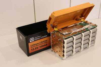
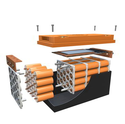
Die Firma LIONTRON ist mir auf der BOOT aufgefallen. Das Akkugehäuse kann geöffnet und die Zellen und/ oder das BMS ausgetauscht werden. Nachhaltiger geht es nicht.
Der Versand (insbesondere Luftfracht) von Lithium Zellen ist nicht einheitlich geregelt. Zurzeit hat jede Fluggesellschaft Ihre eigenen Regeln. Da bietet es sich an, ein paar Reservezellen und ein Ersatz BMS auf Langfahrt mitzunehmen. Problemlose Reparaturen abseits von Zivilisation und Flughäfen sind damit möglich.
Einmal jährlich werden die Reserve-Zellen einzeln mit einem Netzteil auf 3,5V nachgeladen. Ein Netzteil und ein Multimeter. Mehr ist zur Wartung und Ladungserhalt der Reservezellen nicht nötig.
Das BMS hat eine Bluetooth Schnittstelle, um den aktuellen Akkuzustand abzufragen.
Lade-/ Entladestrom und Akkukapazität werden in der App angezeigt.
Technische Daten: 12V 200AH
Temperaturbereich: Entladung: -20°C bis +60°C
Ladung: 0°C bis +45°C
Außerhalb der genannten Temperaturbereiche schaltet das BMS ab.
Die Arctic Versionen gehen von -30°C bis +45°C. Bei Anschluss eines Ladegerätes wird erst eine Heizplatte im Gehäuseinneren angeschaltet bis der Akku auf +5°C aufgeheizt ist. Dann wird der Akku geladen.
Ladeschlussspannung: 14,2-14,4V (BMS schaltet bei 14,65V aus, ab 14,6V wieder ein)
Entladeschlussspannung: 11V (BMS schaltet bei 10,75V Aus und bei 11V wieder ein)
Außerhalb des genannten Spannungsbereiches schaltet das BMS ab.
Der Zellenladungsausgleich erfolgt passiv und arbeitet nur während der Akkuladung. Dabei wird ein Widerstand über die Zelle mit der höchsten Zellspannung angeschaltet und die Zellenspannung damit begrenzt. Die Gesamtkapazität des Akkus richtet sich nach der schwächsten Zelle.
Der Dauerentladestrom beträgt 150A. Wer einen 230V Wandler im kW Bereich betreibt, sollte 2 Akkus parallelschalten. Ist der Entladestrom>= 200A / pro Akku wird er nach 20sek abgeschaltet.
Kosten:
Rechenbeispiel: 2x 12V 200AH LIONTRON kosten ca. 3.600€
50% Entladung: 2x 12V x 0,5 x 200Ah * 5.000zyklen = 12.000kWh für das Batterieleben
3.600€ Batteriekosten/ 12.000kWh = 0,30€ / kWh
Wobei der Akku auch mal bis 10% bis 20% Restkapazität entladen werden kann ohne großartig Zyklen zu verlieren. Wenn es aber notwendig sein sollte, steht dem Nutzer aber eine fast doppelte Nutzungszeit aus dem Service Akku zur Verfügung.
5 Jahre Hersteller Garantie. Gewicht: 26kg pro Batterie
Smartphone App:
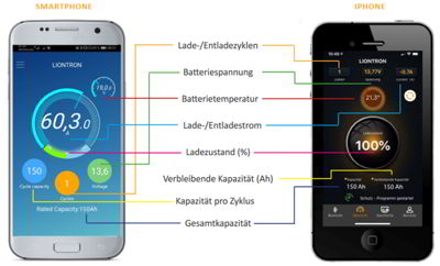
Für die Akkumulatoren von LIONTRON wird ein Smartphone APP zur Anzeige der wichtigsten Parameter kostenfrei im App Store heruntergeladen werden.
Parameter des BMS können nicht abgeändert werden.
Fazit:
Ein problemloser, nachhaltiger Akku Typ als Ersatz für einen defekten Bleisäure Akku. Lade/ Entladeströme und Kapazitätsanzeige werden über eine Smartphone App angezeigt. Wem der Temperaturbereich des Akkus ausreicht, ist mit diesem Akku auf einem sehr guten Weg.
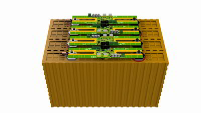
Gründe für Winston LiFeYPo4 Zellen und das BMS der Fa. ECS:
Durchweg gutes bis sehr gutes Feedback über Jahre in den Wohnmobilforen. Zellenhersteller Winston ist schon seit 18 Jahren im Geschäft. Temperaturbereich (Laden und Entladen) von -45°C Temperaturen bis 85°C. Nachhaltigkeit: Einzelne Zellen lassen sich bequem austauschen. Geringe Selbstentladung: Reservezelle kann man mitnehmen. Schnelladefähigkeit bis zu 3C (dreifache Kapazität in A). Nahezu doppelte entnehmbare Kapazität gegenüber Blei Akkumulatoren. 66% Gewichtsersparnis. Sicherheit: Keine Brandgefahr.


12V Winston Akku BMS einer Zelle der Fa. ECS.
Aktives BMS der Fa.ECS:
Aktiver Zellenausgleich auf größtmögliche Kapazität. Anzeige der Akkukapazität, Ladezustände der Zellen und vieles mehr über eigenes LC-Display an der Schalttafel (Auch Smartphone möglich). Im Zusammenspiel mit der Anzeige ist der Aufbau eines intelligentes Akkusystems möglich. Keine besonderen Anforderungen an die Verkabelung. 4 zusätzliche Ausgänge für Alarmmeldungen und 4 zusätzliche Eingänge für Füllstandsmessungen. Weitere Schnittstellen vorhanden. Bereitschaft eines Fachhändlers in Deutschland eine Zelle bzw. BMS ans Ende der Welt nachzusenden. Wobei Ersatzteile auf die Reise mitzunehmen kann u.U. sehr viel günstiger sein.
Die Daten können auch in eine Cloud übertragen werden, das BMS programmiert oder der elektronische Schalter betätigt werden. Damit kann das Akkusystem von zu Hause, über das Internet, gemanagt werden.
LC-Display GreenView:
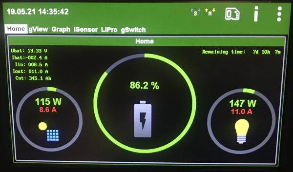
Anzeige aller wichtigen Daten, Ladestrom, Verbraucherstrom, Kapazität, Akku Restlaufzeit usw.
Parametrierung aller Akkuparameter.
Systemschaubild der Ladekomponenten und dem LiFeYPo4 Service Akkumulator
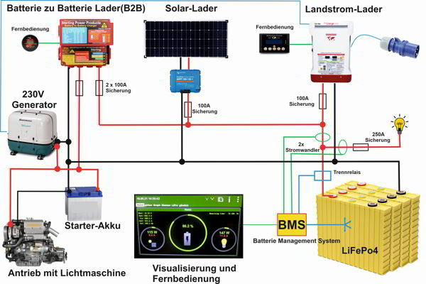
Nach den Erläuterungen zu den einzelnen Lade-Komponenten und des LiFePo4 Akkumulator kommen wir jetzt zur Parametrierung.
Parameter Einstellung (für eine lange Akkumulator Lebensdauer):
Schon mit der Werkseinstellung funktioniert das System aus Akku, BMS, Relais und LC-Display einwandfrei und arbeitet nach den allgemeinen Herstellerparametern. Trotzdem empfiehlt es sich mit dem erfahrenen Lieferanten des Akkus ein beratendes Gespräch über die Akkuparameter bezüglich Lebensdauer, Zyklenfestigkeit und Temperaturprofil zu führen. Die nachfolgend genannten Werte beziehen sich auf normale Umgebungstemperaturen von 5°C – 40°C. Im negativen Temperaturbereich sind geringere Zellspannungen zu berücksichtigen.
Aus vielen Jahren Erfahrungen im Betrieb von LiFePo4 Akkumulatoren wurde festgestellt: Ein geladener LiFePo4 Akku darf nicht ständig an der maximalen Zellspannungsgrenze von 3,65V geladen werden. Ebenso sollte man einen LiFePo4 Akku auch nicht unter 20% Restkapazität entladen.
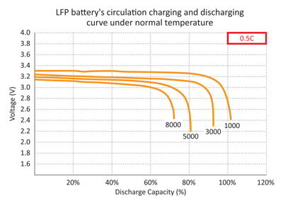
Im Kapitel „Mythen und Wahrheiten“ wurde der Zusammenhang zwischen Entladetiefe und Anzahl / Verlust der Zyklenzahl (= Lebensdauer) eines LiFEPo4 Akkumulators dargestellt.
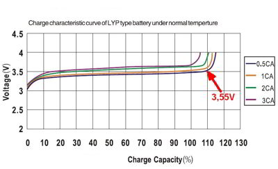
In den Kurven ist es gut zu sehen, dass mit fallenden Ladestrom die maximale Kapazität bei geringeren Ladeschlussspannungen erreicht wird. Daher wurde die maximale Ladespannung auf 3,50V festgelegt. Somit sollten die Ladegeräte 14,2V (max. 14,4V) nicht überschreiten.
Ebenso sollte man die Ladungserhaltung nicht mit 3,45V/ Zelle betreiben, wie in vielen Ladekennlinien enthalten. Hier ist eine Spannung von 3,32V/ Zelle vollkommen ausreichend. Daher wurde für dieses Projekt die Parameter der Ladegeräte wie folgt gewählt: Stromladung (Bulk oder CC = Constant Current genannt) bis 14,2V (= Absorptionsspannung), dann Spannungsladen (Float oder CV = Constant Voltage genannt) mit 13,3V (= Erhaltungsladung). Viele Lader lassen sich mit (fast) geeigneten Kennlinien darauf einstellen, bzw. individuell anpassen.
Hinweis: 0,5CA (aus der Grafik) bedeutet einen Ladestrom von maximal 1/2 der Akkukapazität. Für den gewählten 400Ah Akku bedeutet das 200A maximaler Ladestrom.1CA bedeutet 400A und 3CA 1200A Ladestrom.
Anpassung der Ladekomponenten an den LiFePo4 Akkumulator
Landstrom Lader: Sterling Pro Charge Ultra 12V 60A
LiFePo4 Kennline: 14,8V Bulk/ 13,8V Float (Werte sind zu hoch, daher Custom Kennline einstellen)
Custom Kennlinie: 14,2V Bulk/ 13,3V Float.
Bei Abwesenheit von Bord wird das Ladegerät abgeschaltet bzw. in Standby geschaltet.
Sollte für diesen Lader ein Austausch anstehen, wird ein 12V 200A Lader zum Einsatz kommen.
Solar Lader: Victron Smart Solar MPPT 100/50; maximaler Ladestrom 30A
LiFePo4 Kennlinie: 14,2V Bulk / 13,5V Float. Die Kennlinie wird eingestellt, passt aber nur im oberen Wert (Absorptionsspannung). Der untere Wert (Erhaltungsspannung) muss manuell auf 13,3V geändert werden. Zusätzlich ist der Parameter Re-Bulk Offset auf 0,1V und die Absorptionsdauer auf variabel zu setzen. Das geht mit der zugehörigen Smartphone App ganz einfach. Die Einstellung wird als „An Bord“ im Smartphone gespeichert.
Bei Abwesenheit von Bord wird der Parameter Bulk und Float auf 13,3V gesetzt und als „Von Bord“ in der App gespeichert. Damit wird die Akkukapazität gehalten, ohne den Akku zu überladen.
Batterie zu Batterie Lader (B2B): Sterling BBW1260 12V / 60A
LiFePo4 Kennlinie: 14,4V Bulk / 13,8V Float. Die Werte sind zu hoch daher wurde die Custom Kennlinie gewählt. Custom Kennlinie: 14.2V Bulk/ 13,3V Cond/ 13.3V Float.
Achtung: Die Custom Kennlinie kann nur über die Fernbedienung angewählt werden. Segler, die diesen B2B Lader ohne Fernbedienung verbaut haben, nehmen die AGM Kennlinie: 14.1V Bulk/ 13,75V Konditionierung / 13.4V Float (passt nicht so schön, ist aber ok).
Damit hat man die Ladekomponenten eingestellt und den Übergang von AGM auf LiFePo4 Akkumulatoren einfach geschafft.
Umfrage bei den Kasko-Versicherungen:
Eine Nachfrage bei den üblichen Kasko Versicherern ergab keine Einschränkung für die Nutzung von LiFePo4 Akkumulatoren auf Yachten. Auch nicht für die hier vorgestellte Zusammenstellung aus Akku- Zelle, BMS und Visualisierung. Die Bauteile müssen geltenden Bauvorschriften entsprechen (CE Zeichen). Alle Lieferanten in Deutschland und Europa unterliegen der Pflicht zur CE Prüfung. Wichtiger sind die Normen für den fachgerechten Aufbau, Kabelstärken, stabiler Aufbau, doppelter Schutz gegen Überströme wie elektronische und mechanische Sicherungen, etc.
Jedoch sollte man sich immer im Vorfeld mit der Kasko-Versicherung seines Vertrauens auseinandersetzen. Der Versicherer könnte dem Eigner ansonsten eine Obliegenheitsverletzung vorwerfen, sollte es zu einem Schadenfall kommen, der auf die Akkus zurückzuführen ist.
Manche Versicherungen, (die mit dem P…) verlangen den Einbau und Abnahme von zertifizierten Fachbetrieben, (Totschlägerargument, um nicht in Leistung treten zu müssen). Alle anderen Versicherungen haben keinerlei weiteren Einschränkungen, außer den zuvor genannten.
Kostenaufstellung: (wenn man jetzt alles neu kaufen müsste)
Sterling Ultra Charge: 620€ + 110€ Fernbedienung
Sterling Batterie to Batterie Lader: 400€ + 100€ Fernbedienung
2x Liontron Batterie 12V 200Ah: 3600€
oder
Batterie Set Winston LiFePo4 mit 4 x aktivem BMS, elektronischer Schalter und
LC-Anzeigepaneel: 3400€
Solarpanel 24V (5 Busbars, 360W) 390€
Vitron MPPT 100/50 Solarregler mit Kennlinie 300€
200A Streifensicherung mit Halter: 75€
Elektronische Last DL24: 25€-40€
Kabel, Kabelschuhe, Siebdruckplatten, Sicherungen
Steuerleitung, etc.: 130€
Erfahrungen aus 9 Monaten Betriebszeit mit dem neuen LiFeYPo4 Akku:
Kein Zusammenbruch der Versorgungsspannung bei höheren Lasten. Sehr kurze Ladezeiten und daraus ergebenen kurzen Maschinen-/ Generatorlaufzeiten. Sehr gute Übersicht über den Ladezustand des Akkus. Sehr frühe Bereitstellung von Ladung aus dem Solarpanel. Entspanntes Reisen ohne Landstromanschluss. Notwendige Motorlaufzeiten haben zur Nachladung immer gereicht.
Kurzum die Umrüstung war ein voller Erfolg.
Fazit:
Diesen Bericht wurde aus mehreren Quellen zusammengefasst. Es ist keine wissenschaftliche Arbeit und daher verweisen wir auf keine Quellen, es ist mehr eine Art Beitrag zur Informationsvermittlung mit dem Ziel, Ihnen mehr Verständnis über diese Lithium-Akku-Technologie zu verschaffen.
Er ist aus der Notwendigkeit entstanden ein vorhandenes Stromversorgungsnetz an Bord zu erneuern und zu modernisieren. Die drei Blei AGM Akkus mit 600Ah wurden in diesem Projekt durch einen LiFeYPo4 Akkumulator mit 400Ah ausgetauscht. Haben Sie Kritik, Anregung, Korrektur- und / oder Ergänzungsvorschläge, fühlen Sie sich frei, sich damit an mich zu wenden.
Zusammenbau einer 12V Service Batterie mit 400Ah auf Basis von Winston LiFeYPO4 Zellen inklusive BMS.
Sie können eine reich bebilderte und ausführliche Bauanleitung mit Bezugsquellen vom Palstek-Server laden.
Copyright by Jochen Brickwede
Im Januar 2022
- Details
- Zugriffe: 11302
SD40 / SD50 Saildrive drucklos umbauen
(Saildrive Ölwechsel im Wasser schwimmend)
Auf meinem Youtube Kanal ist ein Video verfügbar.
Sie haben schon einmal Spuren von Getriebe Öl auf dem Dichtungsflansch des Saildrive entdeckt? Das könnte auf einen falschen Ölstand im SD50 hinweisen. Sie wechseln das Öl selbst im Rahmen der jährlichen Wartung und folgen den Anweisungen Ihrer Betriebsanleitung? Sie lassen den Ölwechsel in einer Yanmar Service Werkstatt machen? Aber auch die Service Werkstätten lesen nicht alle die Yanmar Technical Bulletin.
In dem Yanmar Technical Bulletin MSA 09-017(vom 16.9.2009) wird der Ölstand im SD50 neu definiert.
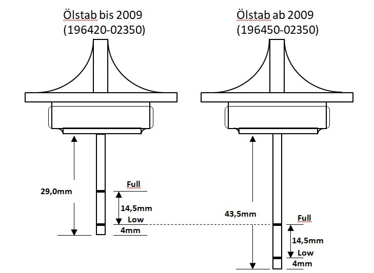
Schauen Sie also nach ob in Ihrem SD50 ein langer oder kurzer Ölmessstab verbaut ist, und befüllen Sie den SD50 nur bis zur Low Markierung beim kurzen Ölmessstab oder bis zur Full - Markierung des langen Ölmessstabs. Durch die Erwärmung im Betrieb des SD40/SD50 baut sich im Getriebe ein Druck auf. Dieser Druck könnte über den Antriebswellendichtring (zum Motor) entweichen. Dabei kann Getriebeöl mit austreten. Bei der anschließenden Abkühlung könnte ein Unterdruck im SD40/ SD50 entstehen, welcher Wasser am Propellerdichtring ansaugen könnte.
Durch die Änderung am Ölstand und der damit verbundenen Vergrößerung des Verhältnisses von Luft zu Ölstand im SD40/SD50 sind die Druckverhältnisse günstiger und das Risiko einer Wasser in Öl Leckage geringer. Yanmar hat zu diesem Zweck auch einen neuen Ölstab herausgebracht. Ein neuer Ölmessstab kann unter der Ersatzteilnummer 196450-02350 beim Yanmar Service bestellt werden.
Was wäre denn, wenn das Saildrive im Betrieb drucklos gehalten werden kann, kein Öl am Motor-Simmerring austritt und der Ölstand trotzdem auf „Maximal“ Pegel stehen könnte?
Mit der nachfolgenden Anleitung wird das SD40/ SD50 Saildrive so umgebaut, dass es im Betrieb drucklos bleibt.
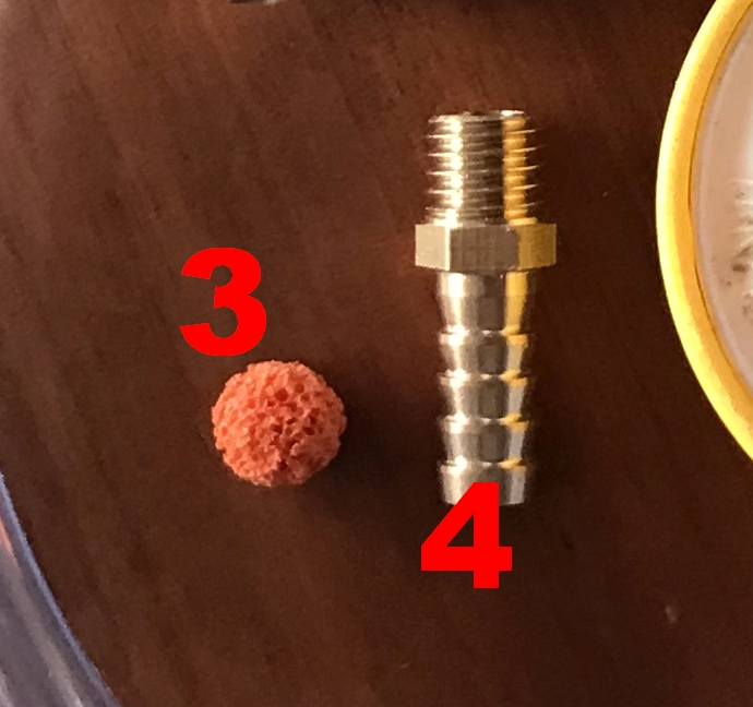
Teile Liste:
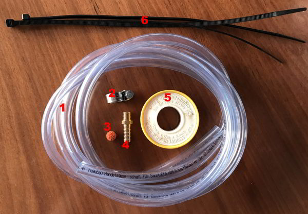
1: 10mm PVC-Schlauch, 2m lang (Baumarkt oder Ersatzteilkiste an Bord).
2: Niro Schlauchschelle für 10mm Schlauch (Baumarkt oder Ersatzteilkiste an Bord).
3: Kugelschwämmchen für 10mm Schläuche (Service Kit)
4: Messingadapter M10x1,5-10mm (Service Kit)
5: Teflonband (Baumarkt oder Ersatzteilkiste an Bord).
6: 5x Kabelbinder verschiedene Längen (Baumarkt oder Ersatzteilkiste an Bord).
Die Teile 3 und 4 sind evtl. im Einzelhandel schwierig zu bekommen.
Einfach die Bestellliste laden, die gewünschten Teile ankreuzen und die Datei mir zusenden. (Info: Die Datei läßt sich im Acrobat Reader direkt bearbeiten.)
Oder mir eine Mail schreiben
Die Teile 3 und 4 können von mir bezogen werden (18€ (25€ mit 2 Messingadapter) incl. Versand). Einfach eine Mail schreiben. Alles andere bekommt man im Baumarkt.
Der Umbau:
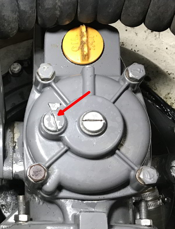
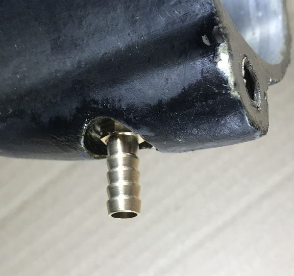
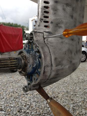
Links: An dem oberen Kupplungsdeckel wird die markierte Schraube entfernt.
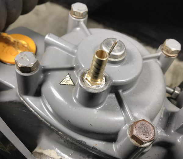
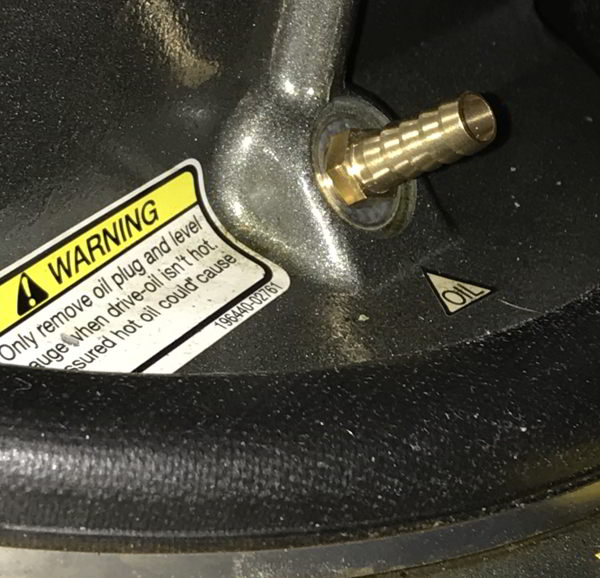
Rechts: Die 10mm Messingadapter wird mit etwas Teflonband eingeschraubt und gedichtet
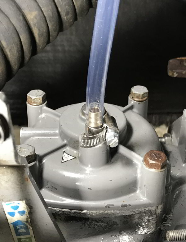
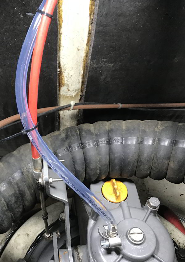
Links: Der 10mm Schlauch wird auf die Schlauchtülle gesteckt und mit der Schlauchschelle befestigt. Klarer Weich-PVC-Schlauch ist überwiegend ölfest und man kann sehen, ob Öl austritt. Ein paar cm Öl in der Leitung ist kein Problem.
Mitte: Der Schlauch mit den Kabelbindern in einem weitem Bogen an anderen Teilen im Motorraumnach oben geführt.
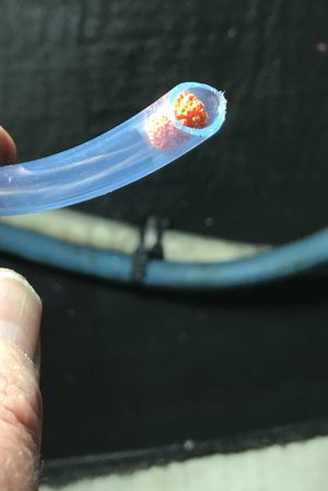
Rechts: Am Schlauchende wird ein kleiner Schaumgummiball in den Schlauch gesteckt, um Staub und Insekten den Zutritt zu verwehren.
Bei Erwärmung kann nun der Druck entweichen. Selbst kleine Mengen Öl kann der Schlauch ausgleichen. 1m Schlauch mit 10mm Innendurchmesser nimmt 70ml Öl auf.
Getriebeölwechsel am Saildrive unterwegs.
Im Saildrive-Betriebshandbuch von 2009 wird der Ölwechsel ab Seite 42, in der Saildrive-Bedienungsanleitung von 2004 im Kapitel 6.2.1. beschrieben. Der Messingadapter kann auch am Ölauslass eingeschraubt werden.
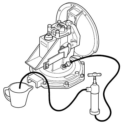
Links: Die Schlauchtülle M10 x 1,5 aus dem Drucklos Service Kit kann auch in den unteren Teil des Saildrive (Bodenplatte) eingeschraubt werden.
Rechts: Die Schlauchtülle wird am Ölauslass eingeschraubt und mit einer Hand- oder elektrischen Pumpe kann das ÖL abgepumpt werden. (Zeichnung: Yanmar Betriebshandbuch).
Inwieweit das Öl (oder durch Leckage mit Seewasser verdickte Öl) so entfernt werden kann, kann ich leider nicht beurteilen. Darüber gibt es keine Informationen.
Eine sehr gute Methode die pastöse Masse aus dem Saildrive zu entfernen wäre eine Spülung mit heißem Öl. Doch wie spüle ich ein Saildrive mit Boot im Wasser schwimmend?
Zum Glück passt die Schlauchtülle auch an der unteren Ölablassschraube vom Saildrive.
Schritt 1: Wenn das Getriebeöl schon an die Konsistenz von Mayonnaise kommt, sollte es erst warmgefahren werden.
Schritt 2: Das Saildrive wird am Peilstab mit Getriebeöl vollgefüllt. Die evtl. vorhandene Getriebeentlüftung, auch die Entlüftung im Deckel, wirdn abgebaut.
Schritt 3: Die Ölablassschraube wird unter Wasser geöffnet und (mit Dichtung!) entfernt. Weiteres Wasser kann nicht eindringen, weil Öl leichter als Wasser ist und im randvoll ölgefülltem Getriebe kein Platz für zusätzliches Wasser ist.
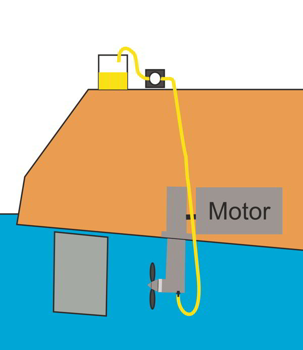
Schritt 4: Die Schlauchtülle, an dem nunmehr ein ausreichend langer 10mm Schlauch angebracht ist, wird vorsichtig (damit das Gewinde nicht beschädigt wird) anstatt der Ölablassschraube eingedreht. Das andere Ende des Schlauch befindet sich dabei im Cockpit, angeschlossen an einer Getriebeöl-Pumpe. (rechtes Bild)
Schritt 5: Die Öleinfüllöffnung am Peilstab wird geöffnet und das Öl über den Schlauch/ die angeschlossene Pumpe abgesaugt. In das Getriebe wird so lange Öl nachgefüllt, bis nur noch sauberes Öl abgesaugt werden kann.
Schritt 5a: Man könnte auch mit heißem, dünnflüssigem Motoröl spülen, d.h. wenn das Öl warm in der Pumpe ankommt, den Schlauch am Ölpeilstab in das Saildrive einfüllen und einige Zeitlang das Getriebe spülen. Zusätzlich könnte das Getriebe mit Leerlaufdrehzahl im Rückwärtsgang (damit der Schlauch nicht in den Propeller gerät) bewegt werden, um noch festsitzende Öl-Mayonnaise zu lösen. Anschließend wird das Spül-Öl mit der endgültigen Getriebeölfüllung ausgetauscht.
Schritt 6: Das Getriebe wird wieder randvoll - wie oben - mit Öl gefüllt.
Schritt 7: Den Messingadapter wird gegen die Ölablassschraube nebst Dichtung ausgetauscht und festgezogen. Wasser kann nicht eindringen, da das Saildrive randvoll mit Öl ist. Ein Ölaustritt ist, wenn überhaupt, minimal da Öl leichter als Wasser ist.
Schritt 8: Der Ölstand im Getriebe wird wieder mit dem Ölpeilstab auf „Max“ eingestellt. Die Saildrive Entlüftung wieder angeschlossen.
Fazit: Das eigentliche Problem, nämlich die wahrscheinlich schadhaften Dichtungen an der Propellerwelle, ist damit noch nicht gelöst. Aber vielleicht findet sich noch eine Werft, ein Kran oder eine Sandbank mit ausreichend Tide (für einen Katamaran). Zeit genug zum Nachdenken hat der Bootseigner jetzt gewonnen.
Noch ein Hinweis:
Wer eine Tauchausrüstung, bzw. einen elektrischen Kompressor an Bord hat, für den ist der Austausch von Schlauchtülle und Ölablassschraube Unterwasser um ein Vielfaches einfacher.
Dazu gibt es noch einen weiteren Bericht "Kompessor an Bord".
Noch ein Wort zum Getriebe Öl
In der Betriebsanleitung zum SD50 wird auf das Mercury Qucksilver High Performance Gear Oil hingewiesen. Soweit bekannt, wird diesem Öl nicht nur ein exorbitanter Preis, sondern auch sehr gute Wasserbindungs - Eigenschaften zugeschrieben. Beides kann ich bestätigen.
Wenn man die Simmerringe am Propeller des Saildrives zusammen mit dem Unterwasseranstrich immer wechselt, so alle 2-3 Jahre, kann man auf diese Eigenschaften gut verzichten und verwendet SAE 90 GL3 oder GL4 Getriebe ÖL stattdessen. Das kostet nur 10% - 15% des Quicksilver Öl Preises und ist vollkommen ausreichend für die Belastungen im Saildrive.
Auf keinen Fall GL4+ oder GL5 oder noch höher legierte Öle verwenden. Diese sind nicht nur teurer, sondern definitiv nicht gut für die Kegelkupplung.
Und nun für die Techniker unter den Seglern:
Ein API GL4 Schmierstoff enthält Additive speziell für Schaltgetriebe. Schaltgetriebe enthalten Buntmetall (Synchronringe). Die Reibung eines GL4 Öls darf nicht zu gering sein, sonst rutscht der Synchronring durch und schalten wird unmöglich. Ist die Reibung zu hoch, wird die Schaltung hakelig und kratzt. Der Kegel in der SD50 Kupplung ist aus Buntmetall. Eine zu geringe Reibung würde die Kupplung leicht durchrutschen lassen.
Auch kein GL4+oder GL4/5 verwenden. Das ist dünnflüssig wie GL5 und enthält nicht so scharfe Additive.
Ein API GL5 Schmierstoff enthält spezielle Additive für höchstbelastete Getriebe, wie z. Bsp. Hypoidgetriebe. Diese Getriebe haben eine Bogenverzahnung. Neben einigen Vorteilen hat diese Art der Verzahnung den Nachteil das die Flächen nicht nur aufeinander abrollen, sondern auch ein wenig gleiten. Das stellt erhöhte Anforderungen an das Material und benötigt eine hohe Gleitfähigkeit des Öls. Die Additive enthalten Schwefel, was wiederum Buntmetalle angreift.
Gang rein oder Getriebeleerlauf beim Segeln?
Im Internet kursieren die wildesten Gründe warum der Gang eingelegt oder das Getriebe im Leerlauf mitlaufen sollte. In bestimmten Fällen stimme ich der Yanmar Anweisung zu. Bei einem Festpropeller muss das Getriebe im Leerlauf mitlaufen. Bei einem Faltpropeller muss man prüfen, ob ein eingefalteter Propeller Schwingungen auf die Getriebekupplung überträgt.
Begründung: Ist beim Segeln der Gang eingelegt umströmt das Wasser verwirbelnd die Schiffsschraube und erzeugt Schwingungen. Die Schwingungen übertragen sich auf den Kupplungskegel, der in der Kupplungsglocke sitzt. Diese Schwingungen erzeugen kleine Bewegungen, die die Kupplungsglocke polieren und führt dazu, dass die Kupplung nicht mehr greift. Eine rutschende Kupplung ist die Folge.
Fake Argument: „Nicht richtig geschmiert“. In Internet wird behauptet, dass das Saildrive nicht richtig geschmiert würde, wenn es in neutral Stellung beim Segeln mitlaufen würde. Im Benutzerhandbuch des Saildrive SD50 wird in Kapitel 2 „Technische Spezifikation“ unter Schmiersystem „Ölbad Typ“ genannt. Bei diesem Typ sind alle beweglichen Teile immer von Öl umflossen. Eine Pumpe ist nicht notwendig. Somit ist dieses Argument falsch.
Fake Argument: „Hohe Abnutzung“. Was soll sich abnutzen, wenn der Wasserstrom den Propeller und das Getriebe bis zur Kupplung antreibt? Die Kraft ist viel zu gering, um eine Abnutzung zu erzeugen.
Kommentare, Anfragen und Hinweise via Mail sind immer willkommen.
Haftungsausschluss:
Diese Anleitung wurde nach bestem Wissen und Gewissen anhand einem von mir selbst durchgeführten Reparatur/ Wartung durchgeführt und verschriftlicht.
Die Anleitung wurde sorgfältig von mir erstellt und geprüft. Es wird keine Haftung für die Anwendung dieser Anleitung oder für Beschädigungen, die durch diese Anleitung entstehen, übernommen.
Copyright:
Jochen Brickwede im April 2023
- Details
- Zugriffe: 15042
Convert SD40 / SD50 Saildrive without pressure
(Saildrive oil change floating in the water)
Have you ever noticed traces of gear oil on the sail drive sealing flange? This could indicate an incorrect oil level in the SD50. Do you change the oil yourself as part of the annual maintenance and follow the instructions in your operating manual? Do you have the oil changed at a Yanmar service workshop? But even the service workshops do not all read the Yanmar Technical Bulletin.
The oil level in the SD50 is redefined in the Yanmar Technical Bulletin MSA 09-017 (dated 16.9.2009).
So check whether your SD50 has a long or short dipstick and only fill the SD50 up to the low mark on the short dipstick or up to the full mark on the long dipstick. As the SD40/SD50 heats up during operation, pressure builds up in the gearbox. This pressure could escape through the drive shaft seal (to the engine). Gear oil can escape as well. During the subsequent cooling, a negative pressure could arise in the SD40/ SD50, which could suck in water at the propeller sealing ring.
Due to the change in the oil level and the associated increase in the ratio of air to oil level in the SD40/SD50, the pressure conditions are more favorable and the risk of water-in-oil leakage is lower. Yanmar has also released a new dipstick for this purpose. A new dipstick can be ordered from Yanmar Service using part number 196450-02350.
What would happen if the sail drive could be kept depressurized during operation, no oil escaped from the engine oil seal and the oil level could still be at "maximum" level? With the following instructions, the SD40/ SD50 Saildrive is converted so that it remains depressurized during operation.
Parts list:
1: 10mm PVC hose, 2m long (hardware store or spare parts box on board).
2: Stainless steel hose clamp for 8mm hose (hardware store or spare parts box on board).
3: Ball sponge for 10mm hoses (service kit)
4: hose connector M10x1.5-10mm (service kit)
5: Teflon tape (hardware store or spare parts box on board).
6: 5x cable ties of different lengths (hardware store or spare parts box on board).
Parts 3 and 4 may be difficult to obtain individually.
Simply load the order list, tick the parts you want and send me the file. (Info: The file can be edited directly in Acrobat Reader.)
Or write me an email
Parts 3 and 4 can be obtained from me (18€ (25€ for two) incl. shipping in Germany, abroad on request). Just write an email. You can get everything else at the hardware store.
Another tip. The Saildrive manual describes the oil change
in the water in chapter 6.2.1. described. The hose nozzle can also be screwed into the oil outlet.
SD50 non-pressurized service kit with 2 hose nozzles 25 € incl. shipping in Germany, abroad on request.
The modification:
Left: The marked screw is removed from the upper clutch cover.
Right: The 10mm hose nozzle is screwed in and sealed with some Teflon tape
Left: The 10mm hose is put on the hose nozzle and fastened with the hose clamp. Clear soft PVC hose is mostly oil proof and you can see if oil is leaking out. A few cm of oil in the line is not a problem.
Center: The hose with the cable ties routed up in a wide arc on other parts in the engine compartment.
Right: At the end of the hose, a small foam rubber ball is inserted into the hose to keep dust and insects out.
When heated, the pressure can now escape. The hose can even compensate for small amounts of oil. 1m hose with 10mm inner diameter takes 70ml oil.
Gear oil change on the Saildrive underway.
In the Saildrive operating manual from 2009, the oil change is described from page 42, in the Saildrive operating manual from 2004 in chapter 6.2.1. described. The brass adapter can also be screwed into the oil outlet.
Left: The hose nozzle M10 x 1.5 from the pressureless service kit can also be screwed into the lower part of the sail drive (bottom plate).
Right: The hose nozzle is screwed into the oil outlet and the oil can be pumped out with a hand or electric pump. (Drawing: Yanmar Operations Manual).
Unfortunately, I cannot judge to what extent the oil (or oil thickened with seawater due to leakage) can be removed in this way. There is no information about this.
A very good method of removing the pasty mass from the Saildrive would be to flush it with hot oil. But how do I rinse a sail drive with a boat floating in the water?
Fortunately, the hose nozzle also fits on the lower oil drain plug from the sail drive.
Step 1: If the gear oil has already reached the consistency of mayonnaise, it should first be warmed up.
Step 2: The Saildrive is filled with gear oil using the dipstick. Any transmission ventilation that may be present, including the ventilation in the cover, will be removed.
Step 3: The oil drain plug is opened under water and (with seal!) removed. No more water can get in because oil is lighter than water and there is no room for additional water in the gearbox that is filled to the brim with oil.
Step 4: The hose nozzle, to which a sufficiently long 10mm hose is now attached, is screwed in carefully (so that the thread is not damaged) instead of the oil drain plug. The other end of the hose is in the cockpit, connected to a transmission oil pump. (right picture)
Step 5: The oil filler opening on the dipstick is opened and the oil is sucked out via the hose/the connected pump. Oil is refilled in the gearbox until only clean oil can be extracted.
Step 5a: You could also flush with hot, thin engine oil, i.e. when the oil arrives warm in the pump, fill the hose on the oil dipstick into the Saildrive and flush the gearbox for a while. In addition, the gearbox could be moved with idle speed in reverse (so that the hose does not get caught in the propeller) to loosen oil mayonnaise that is still stuck. The flushing oil is then replaced with the final transmission oil filling.
Step 6: The gearbox is again filled to the brim - as above - with oil.
Step 7: The brass adapter is replaced with the oil drain plug and seal and tightened. Water cannot penetrate as the Saildrive is filled to the brim with oil. Oil spillage is minimal, if any, since oil is lighter than water.
Step 8: The oil level in the transmission is set to "Max" again using the oil dipstick. Reconnected the saildrive vent.
Conclusion: The actual problem, namely the probably defective seals on the propeller shaft, has not yet been solved. But maybe there is still a shipyard, a crane or a sandbank with enough tide (for a catamaran). The boat owner has now had enough time to think.
Another note:
If you have diving equipment or an electric compressor on board, it is much easier to replace the hose nozzle and oil drain plug underwater.
A word about gear oil
The SD50 operating instructions refer to Mercury Quicksilver High Performance Gear Oil. As far as is known, this oil is not only attributed an exorbitant price, but also very good water-binding properties. I can confirm both.
If you always change the Simmerrings on the propeller of the Saildrive together with the underwater paint, so every 2-3 years, you can do without these properties and use SAE 90 GL3 or GL4 gear oil instead. This costs only 10% - 15% of the Quicksilver oil price and is perfectly adequate for the loads in the sail drive.
Never use GL4+ or GL5 or even higher alloyed oils. Not only are these more expensive, but they are definitely not good for the cone clutch.
And now for the technicians among the sailors:
An API GL4 lubricant contains additives specifically for manual transmissions. Manual transmissions contain non-ferrous metal (synchronizer rings). The friction of a GL4 oil must not be too low, otherwise the synchronizer ring will slip and shifting will become impossible. If the friction is too high, the shifting becomes notchy and scratches. The cone in the SD50 clutch is made of non-ferrous metal. Too little friction would cause the clutch to slip easily.
Also do not use GL4+ or GL4/5. This is thin like GL5 and doesn't contain as harsh additives.
An API GL5 lubricant contains special additives for highly stressed gears, such as E.g. hypoid gear. These gears have curved teeth. In addition to some advantages, this type of gearing has the disadvantage that the surfaces not only roll off each other, but also slide a little. This places increased demands on the material and requires the oil to have high lubricity. The additives contain sulphur, which in turn attacks non-ferrous metals.
In gear or in neutral when sailing?
The wildest reasons why the gear should be engaged or the gearbox should run in neutral are circulating on the internet. In certain cases I agree to the Yanmar instruction. In the case of a fixed-pitch propeller, the gear must run in neutral. With a folding propeller, it is necessary to check whether a folded propeller transmits vibrations to the gear coupling.
Reason: If the gear is engaged while sailing, the water flows around the ship's propeller in a turbulent manner and generates vibrations. The vibrations are transmitted to the clutch cone, which sits in the clutch bell. These vibrations create small movements that polish the clutch bell and cause the clutch to lose engagement. The result is a slipping clutch.
Fake argument: "Not properly lubricated". It is claimed on the internet that the sail drive would not be properly lubricated if it were to run in the neutral position while sailing. In the user manual of the Saildrive SD50 in chapter 2 "Technical specification" under lubrication system "Oil bath type" is mentioned. With this type, all moving parts are always surrounded by oil. A pump is not necessary. So this argument is wrong.
Fake argument: "High wear". What is meant to wear out when the water flow drives the propeller and gear up to the clutch? The force is far too low to cause wear.
Comments, inquiries and hints via mail are always welcome.
Disclaimer:
These instructions were carried out and written to the best of my knowledge and belief based on a repair/maintenance I carried out myself.
The instructions were carefully created and checked by me. No liability is assumed for the use of these instructions or for damage caused by these instructions.
Copyright:
Jochen Brickwede in April 2023
- Details
- Zugriffe: 10282
Yanmar 3JH3 Motoröl Auswahl (Gilt auch für viele andere Saug Dieselmotoren)
Da ich des Öfteren nach dem verwendeten Motoröl in dem 40PS Yanmar 3JH3 Motor gefragt werde, hier meine Erfahrung.
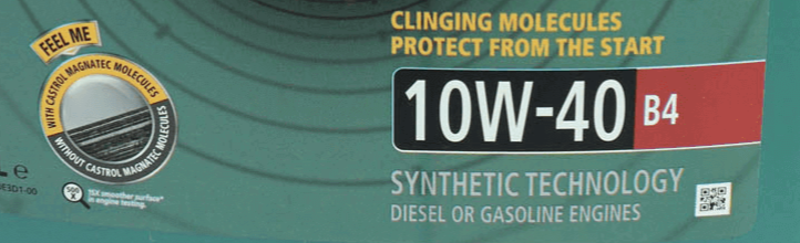
Als Motoröl verwende ich seit Jahren Castrol Magnatec Diesel 10W-40 B4. 10W-40 weil es kein voll-synthetisches, sondernein Öl mit mineralischer Basis ist. Synthetische Öle sind dünnflüssig und lösen gerne Ölablagerungen in älteren Motoren. Wenn Sie nicht wissen, was verwendet worden ist, immer mineralisches Öl verwenden. Insbesondere bei älteren Motoren mit einigen Betriebsstunden auf der Uhr. Sonst könnten sich durch gelöste Ölkohle die feinen Öl Kanäle im Motor verstopfen. B4 ist für Dieselmotoren.
Vor Jahren habe ich die Yanmar Ölspezifikation an Castrol weitergeleitet. Die werben damit, dass der Ölfilm lange auf den Zylinderwänden kleben bleibt, auch bei langen Standzeiten und beim Starten die Reibung reduziert. Die Antwort war: Das Öl wäre noch viel zu gut für einen 3JH3 Motor.
Light Load Situation
Wenn ein Verbrennungsmotor und insbesondere ein Dieselmotor mit weniger als 50% seiner Leistung belastet wird, ist dies extrem schädlich.
Wenn ein Verbrennungsmotor direkt mit der Propellerwelle verbunden ist, steht die Drehzahl des Motors in einem festen Verhältnis zum Propeller und damit auch zur Geschwindigkeit. Da sich der Rumpfwiderstand jedoch nicht proportional zur Geschwindigkeit verhält, ergibt sich ein extremes Missverhältnis.
Zur Erreichung der Rumpfgeschwindigkeit wird zum Beispiel eine Leistung von ca 2,5 kW / 1t Verdrängung gebraucht. Da die Yachten heute fast immer übermotorisiert sind, finden wir in der Praxis aber überwiegend eine Motorleistung von 4 bis 5 kW / 1t. Wenn die so motorisierte Yacht mit 70% der Rumpfgeschwindigkeit bewegt wird, beträgt die Leistungsaufnahme aber nur ca 0,5 kW / 1t. Die aufgrund der Drehzahl effektiv verfügbare Leistung liegt bei 70% der Rumpfgeschwindigkeit so hoch, dass damit das 7 bis 10 fache dessen zur Verfügung steht, als für die Geschwindigkeit erforderlich wäre.
Neben der Vergeudung von Kraftstoff führt die damit verbundene schlechte Abstimmung des Motors zu einer sehr fatalen „Light Load“ Situation mit allen Folgen wie: sehr schlechten Verbrennung, „Verglasung“ der Zylinderwände, Ablagerungen von Verbrennungsrückständen an den Kolbenringen, Übersäuerung des Öls, Korrosion und Teerbildung im Öl mit der Folge eines sehr hohes Zylinder und Lagerverschleißes, hohem Kraftstoffverbrauch und einer sehr starken Abgasbelastung und damit zu einer katastrophal verkürzten Lebensdauer einer Maschine.
Mit der Antriebsmaschine bei 1200U/min den Service Akku zu laden, gehört ebenfalls in die soeben genannte Kategorie und sollte vermieden werden.
Ich stelle den Motor über ein Zugseil ab. Nur nach der Winterpause lasse ich den Motor mit gezogenem Zugseil so lange mit dem Anlasser orgeln, bis Öldruck da ist. Dann ein paar Sekunden warten und dann richtig starten.
Begründung: Nach der Winterpause ist der Ölfilm die Zylinderwände heruntergelaufen und ist noch dünn vorhanden. Ohne Zündung ist der Druck im Verbrennungsraum, damit auf dem Kolben, geringer. Wenn Öldruck vorhanden ist, ist hoffentlich genug Öl auf den Zylinderwänden und der Motor kann starten.
Meine Motoren haben 2980h auf der Uhr. Sie springen immer sofort schnell an. Die Kompression ist somit gut.
Wenn ich Öl brauche, suche im Internet danach. Aktuell 26€ für 5 L ist ok.
Stand: Mai 2021
Seite 2 von 12
Spruch des Monats:
Servicebetriebe verstehen Kundenbindung als die Kunst, den Eigner so schnell über den Tisch zu ziehen, dass er die Reibungshitze als gutes Gefühl empfindet.
Aktuell
Neues Korrosionsproblem bei der Yanmar 3GM30F Maschine gefunden
![]()
Im neuen Palstek 4-26 berichte ich über ein weiteres Korrosionsproblem beim Yanmar 3GM30F Motor. In wie weit weitere Motorentypen dieser Familie betroffen sind wird noch untersucht.
Anschließend erscheint der Bericht hier auf der Webseite.
Wärmetauscher Korrosions Probleme:
Yanmar , Volvo und Vetus sind betroffen
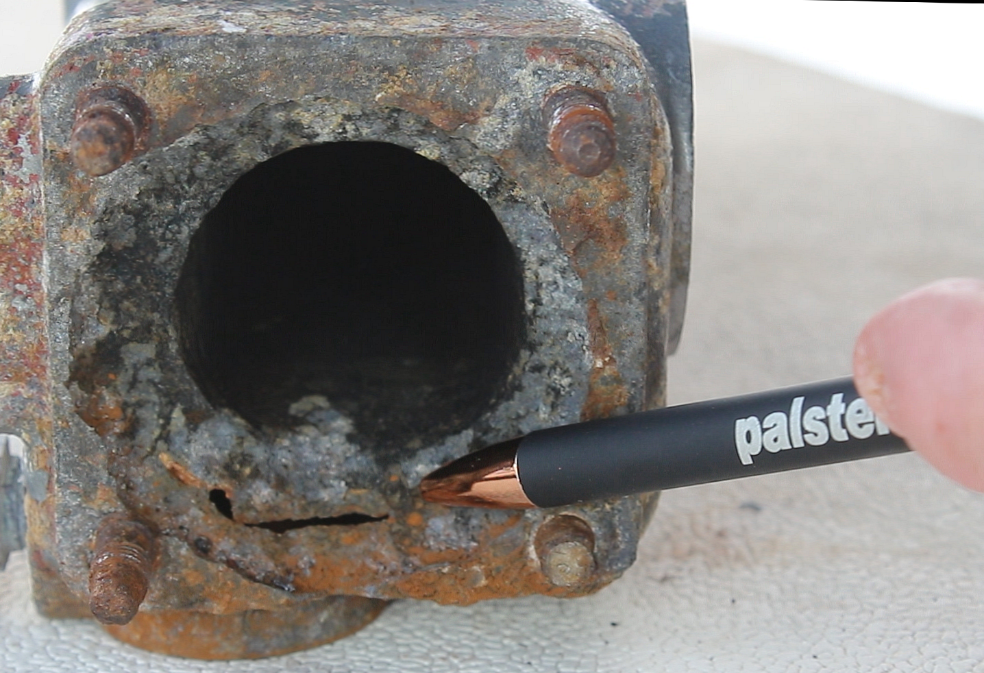
Die im Bild gezeigte Korrosion ist bei den Yanmar Wärmetauschern der 3JH und 4JH Motorenreihe und Volvo D1, D2, D3, MD22, MD22 sicherlich vielen anderen nach 8-12 Jahren üblich. Um das zu verhindern und das Leben des Wärmetauschers zu verlängern sollte der Wärmtauscher vom Abgasmixer elektrisch isoliert werden. Weitere Infos im
![]()
Ausgabe 5-2025 und 1-2026
und auch hier auf dieser Webseite.
Wichtiger Hinweis zum Kupplungsupgrade
Beim Zurückdrücken der 4 Schraubenbolzen kann ein Schaden entstehen. Bitte die Schraubenbolzen über Kreuz, möglichtst gleichzeitig, zurückdrücken. Sonst den Motor verschieben.

Yanmar SD40/ SD50/ SD60 endlich wieder voll ummantelte Dichtringe verfügbar

Endlich hat ein Lieferant wieder voll ummantelte Dichtringe geliefert. Es wird immer schwerer welche zu bekommen.
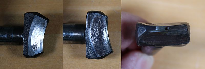
Yanmar SD40/ SD50 Kupplungs Update - Weitere Fehleranalyse Schaltfinger und Kupplungskegel
In dem überarbeiteten Bericht Yanmar SD50 Kupplungsrefit zeige ich die notwendige Analyse um eine weitere Ursache bei einer rutschenden Saildrive Kupplung zu erkennen.
Im meinem Youtube Kanal habe ich ein Video zu dem Thema abgelegt: Tipps und Hinweise zur Technik von Segelyachten (einfach auf den Link klicken)
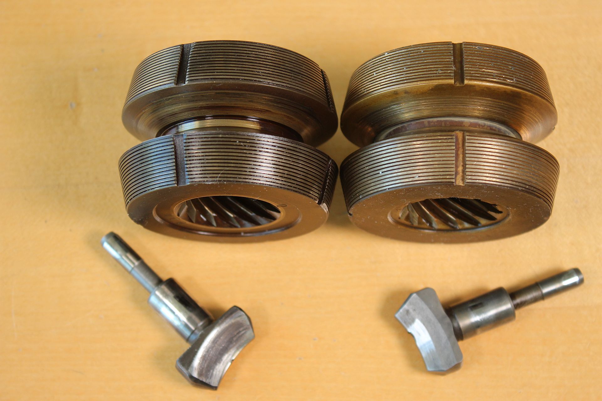
Upgrade Kit für SD40 / SD50 Saildrive Kupplung verfügbar
New SD40/ SD50 clutch upgrade kit
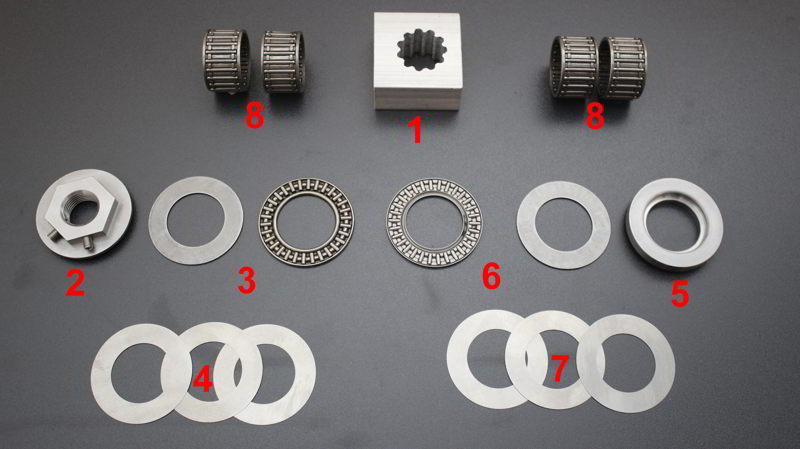
Lager statt Kupferscheiben. Erheblich Verlängerung der Zeit bis zum nächsten Wartung. Bericht hier...
Oder im Youtube Kanal das Video ansehen.....
Kompressor an Bord
(ein Problemlöser für viele Fälle)
Wer schon mal ohne Tauchgerät eine Leine aus dem Propeller geschnitten hat, Seepocken vom Propeller gekratzt hat oder Seepocken vom Rumpf geschabt hat weiß, wovon ich rede. Luftnot, Auftrieb und verlorenes Werkzeug sind die Probleme, die man bei diesen Arbeiten zu lösen hat. Weitere Anwendungen wie verklemmten Anker lösen, über Bord gegangene Teile retten sind weitere Anwendungen.
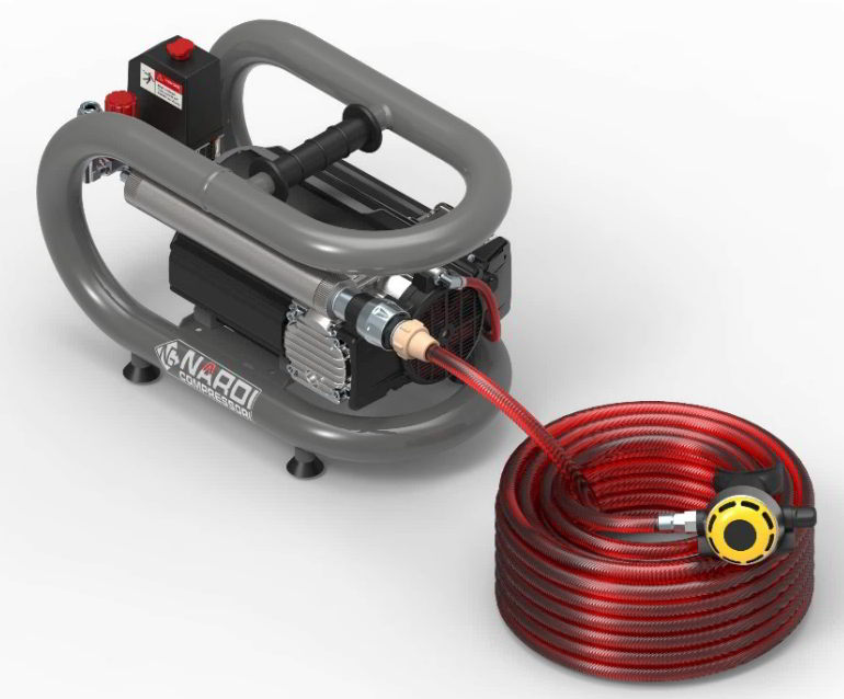
Testbericht über Kompakt Kompressoren an Bord hier....
SD40/ SD50 drucklos umbauen-Ölwechsel im Wasser liegend
SD40/ SD50 Umbaubericht um ein Saildrive drucklos zu betreiben. Siehe Report hier....
Nun auch in englischer Übersetzung:
Convert SD40 / SD50 Saildrive without pressure
Read the report here....
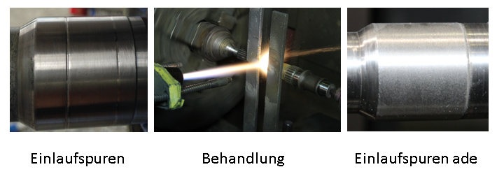
Reparaturbericht zur entgültigen Beseitigung von
Einlaufspuren an der Antriebswelle des Saildrive SD50
![]()
Bericht in der Palstek Ausgabe 2-2022 (März 2022)
Der Bericht ist hier zu finden....
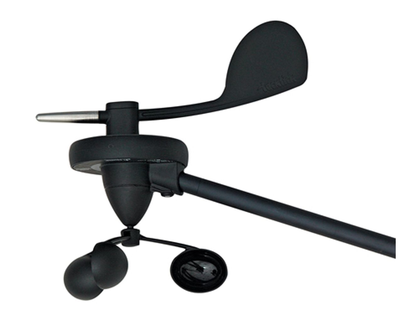
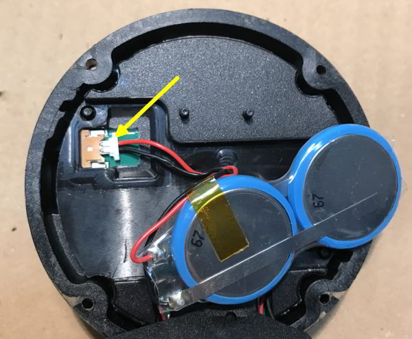
Reparaturbericht zum Raymarine Tacktick T120 Windgeber.
![]()
Bericht in der Palstek Ausgabe 2-2022 (März 2022)
Umstieg von AGM auf LiFeYPo4 Akkumulatoren
![]()
Bericht in der Palstek Ausgabe 1-2022
Nicht erst wenn die Bleiakkumulatoren keine Kapazität mehr liefern, sollte man sich mit der Anpassung und Umrüstung der Stromversorgung an Bord beschäftigen. Damit die Bordversorgung problemlos funktioniert, sollten die einzelnen Komponenten auch zusammenpassen.
Der Bericht (vom Praktiker für den Praktiker) beschreibt die Analyse der Batterien, des Bordnetztes und gibt Hinweise zur Auswahl der Komponenten. Er entstand aus der Notwendigkeit heraus das Bordnetz teilweise zu erneuern, unter Berücksichtigung der vorhandenen Komponenten und gleichzeitig auf einen modernen Stand zu bringen. Nur wenn der Yachteigner seine Bordversorgung kennt, wird er sich im Notfall auch zu helfen wissen.
Der Bericht ist hier zu lesen.
Saildrive SD40/ SD50 drucklos umbauen

Bericht in der Palstek Ausgabe 1-2022
Was wäre denn, wenn das Saildrive im Betrieb drucklos gehalten werden könnte, kein Öl am Motor-Simmerring austritt, die Gefahr des Seewassereintritt durch Unterdruck ins Saildrive gebannt und der Ölstand trotzdem auf dem alten Maximal-Pegel stehen könnte? Mit der gezeigten Anleitung wird das SD40/SD50-Saildrive so umgebaut, dass es im Betrieb drucklos bleibt. Die Bauanleitung ist hier zu finden.
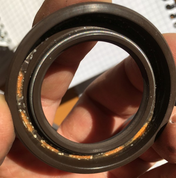
Wie gut ist Original (Yanmar Simmerring für SD50, 196440-02871)? Ein Update vom Bericht in Ausgabe 3-2017.
![]()
Bericht in der Palstek Ausgabe 4-2021
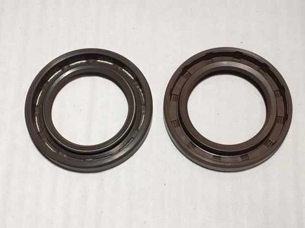
Original-Yanmar-Ersatzteil (links) und Industrie-Typ(rechts). Ein Simmerring besteht aus einem Körper mit innerem Stützring aus rostendem Stahl und einer Dichtlippe, in der eine Schlauchfeder (aus nichtrostendem Stahl) für den richtigen Anliegedruck sorgt.
Über die rostenden Original Yanmar Simmerringe wurde schon in der Ausgabe 3-2017 berichtet. Im Update in der nächsten Palstek Ausgabe wird geprüft, ob sich hier etwas geändert hat oder ob die Simmerringe immer noch nach einem Bad im Salzwasser so aussehen.
Der Bericht ist hier zu lesen.
Tanken bei hohem Seegang aus dem Reservekanister
Bericht in Ausgabe 2/2021

Unterwegs mit dem Segelboot zu sein ist schon eine schöne Sache. Wenn aber Motorunterstützung angesagt ist, hoch am Wind, gegen an oder ein Defekt an der Segelanlage, kann Spritmangel bei hohem Seegang schon lebensbedrohlich werden. Wie bekomme ich den Diesel aus dem Reservekanister in den Tank, ohne etwas zu verschütten oder Meerwasser in die Diesel Einfüllöffnung zu bekommen?
Im Herbst habe ich eine Tankanlage mit 12V Pumpe entworfen und eingebaut. Der Bericht ist der Zeitschrift Palstek 2/21 zu finden.
Der Bericht ist ab sofort auch hier zu lesen.
Yanmar Saidrive SD50 - Kupplungs - Refit (Kupplung rutscht durch)
![]() Bericht in Ausgabe 2/2021
Bericht in Ausgabe 2/2021
Wenn in der ersten oder zweiten Stufe des Schalthebels am Steuerstand der Motor läuft aber kaum Wasser bewegt wird, ist häufig eine rutschende Kupplung die Ursache. Eine rutschende Kupplung kann dem Skipper beim Anleger schon den Schweiß auf die Stirn treiben. In der neuen Palstek 2/21 wird das Läppen der Kupplung Schritt für Schritt beschrieben. Und das Schiff muss auch nicht aus dem Wasser.

Der Bericht ist ab sofort auch hier zu lesen.
Pantaenius - da kann kommen was will - Ausser ein Schaden
Wer kenn sie nicht, die Sprüche der Yachtversicherer.
Aus gegebenem Anlass möchte ich die, bei Pantaenius versicherte, Seglergemeinde auf die in 2017 geänderten Ausschlussbedingungen nach §5 Nr. 2 hinweisen.
Originaler Auszug aus dem Ablehnungsbescheid von Pantaenius:
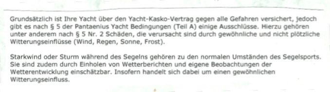
Somit schließt Pantaenius den Schadensausgleich durch Wind, normaler Wind oder Sturm, aus. Ausserdem wird in der Aussage postuliert dass der Wetterbericht so eintritt wie er angesagt wurde. Somit einschätzbar wird.
Ich denke das ist ein wichtiger Punkt. Die Wetterberichte sind in den letzten Jahren zwar genauer in Bezug auf das Eintreffen von Wetterereignissen, aber nicht einschätzbarer in Bezug auf die Stärke der Ereignisse geworden.
Ich habe die Versicherung bei diesem Versicherer gekündigt, das ist doch klar, oder? Ich kann nur jedem Kunden einer Yachtversicherung raten, die Ausschlussbedingung genau zu studieren und ggf. nachzufragen wie manche Bestimmungen gemeint sind.
Neue Reparaturberichte auf den technischen Infoseiten
Simmerringtausch und Laufflächenerneuerung am Yanmar Saildrive SD 50 (auch für SD 40)
Ein Reparaturbericht als Schritt für Schritt Anleitung ist >>> hier zu finden.
Wetterbericht als Luft-Strom Animation
Eine sehr interessante Kombination aus Luft-Strom Animation und Wettervorhersage liefert die Seite www.windyty.com
Seefunkwetterberich von DP07 auf 7310kHz und 9560kHz
Montag - Sonntag 9:30Uhr MESZ ; Montag - Samstag zusätzlich um 14:00Uhr; Sonntag um 14:00Uhr auf 9560kHz. Siehe auch www.dp07.com